Ultimate guide to 3D printing files for SLS – what you need to know
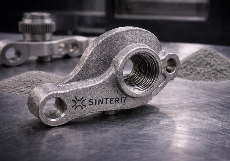
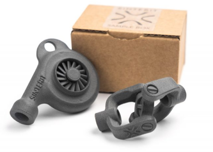
Selective Laser Sintering (SLS) is one of the most powerful 3D printing technologies available today, used widely across industries like aerospace, automotive, and medical device manufacturing. Its ability to produce strong, functional parts without the need for support structures makes it ideal for complex geometries and interlocking components. But this design freedom comes at a cost: your 3D printing file must be meticulously prepared to ensure successful output. Unlike other methods, SLS demands attention to wall thickness, tolerances, orientation, and even nesting strategies. In this guide, we’ll walk you through everything you need to know about creating, optimizing, and exporting 3D printing files specifically for SLS — so your parts print right the first time.
Why file quality matters more in SLS 3D printing
In the world of additive manufacturing, the SLS (Selective Laser Sintering) process stands out for its ability to produce highly complex, functional parts without the need for support structures. However, this capability comes with a unique dependency on the quality and integrity of your 3D printing file.
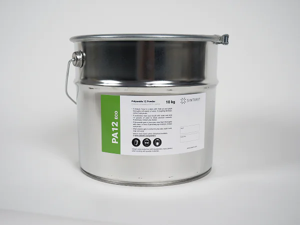
Unlike FDM or SLA, SLS uses a laser to sinter powdered thermoplastics — most commonly PA12 or PA11 — layer by layer inside a heated build chamber. The powder bed itself serves as a natural support, enabling nested parts, moving components, and intricate internal geometries. This freedom, however, increases the importance of a clean, optimized, and accurate digital model. Small errors like non-manifold edges, paper-thin walls, or even incorrect part orientation can compromise the entire print.
That’s why preparing your file for SLS is not just a technical step — it’s a design responsibility.
Choosing the right file format for SLS success
Most designers still use STL as their primary format. It’s simple, lightweight, and universally supported. But STL has its limits. It doesn’t store material data, color, units, or assembly relationships—all increasingly important in industrial SLS use cases.
For that reason, formats like 3MF and AMF are becoming more relevant. 3MF, developed specifically for modern 3D printing, allows you to include build metadata, group multiple parts, assign materials, and more. It’s particularly useful when dealing with assemblies or when you need to maintain clear tolerances across multiple files. AMF (Additive Manufacturing File Format) takes things a step further, allowing curved surfaces and complex part definitions that are useful in sectors like aerospace or medical printing.
OBJ also enters the conversation, especially in workflows where texture and visual appearance matter. It can be valuable for previewing, but it’s less robust for engineering-grade SLS builds.
The takeaway? STL works for basic tasks, but for professional, production-grade SLS, 3MF is quickly becoming the smarter choice.
Preparing a 3D model for SLS: more than just exporting
If you think you’re ready to print after just exporting your CAD model, think again. Proper preparation is what separates a successful SLS print from wasted powder.
First and foremost, the model must be watertight — also known as manifold. This means no gaps in the mesh, no non-connected faces, and no internal walls that confuse the slicer. Tools like Autodesk Netfabb, Meshmixer, or Materialise Magics can help detect and fix these issues.
Then comes wall thickness. In SLS, walls thinner than 0.7 mm may survive the printing process but break during post-processing, especially during depowdering or bead blasting. At the same time, overly thick walls can trap powder or increase material costs unnecessarily.
Clearance is another design detail often overlooked. SLS allows printing of moving or interlocking parts in one go, but if there’s not enough spacing — typically at least 0.2 mm — your components may fuse together during sintering.
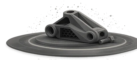
Orientation inside the build chamber also affects performance. Unlike in FDM, parts don’t need support, but how they’re placed influences cooling patterns, strength, and surface texture. A poorly oriented model might warp or exhibit surface artifacts. SLS slicers like Sintert Studio or Formlabs PreForm can help simulate and fine-tune these parameters before you hit “print.”
Finally, there’s nesting — the arrangement of multiple parts inside a single build. Efficient nesting saves time, reduces powder waste, and improves print consistency. Automated nesting tools help optimize part distribution, especially in production workflows.

The role of software in SLS file optimization
While CAD software like Fusion 360 or SolidWorks can produce detailed models, that’s only half the journey. For SLS printing, post-modeling tools play a crucial role in ensuring printability and efficiency.
Mesh repair platforms like Netfabb or Magics analyze files for print errors, fix non-manifold issues, and optimize meshes for sintering. On the slicing side, purpose-built tools such as Sinterit Studio or PreForm (used with Formlabs Fuse) provide control over part layout, orientation, and build simulation — features that are critical in powder-bed fusion systems.
If you’re printing parts with strict tolerances or specific load-bearing requirements, some software platforms even offer simulation modules to predict part deformation, cooling behavior, or powder flow. This insight can significantly reduce trial-and-error cycles.
Where to find (and legally use) SLS-ready files
While the internet is full of downloadable 3D models, not all are created equal — or legally usable.
Mainstream libraries like Thingiverse, MyMiniFactory, or Cults3D are great for hobbyist projects, but most of their content is geared toward FDM or SLA printing. If you’re seeking SLS-optimized models, look toward engineering-focused platforms like GrabCAD or TraceParts. These sites offer higher-resolution, parametric files often created with manufacturing in mind.
Always pay attention to licensing. Creative Commons licenses vary in what they allow: some permit modification and commercial use, while others forbid it. For business or commercial applications, you must ensure the files are in the public domain, royalty-free, or licensed for professional use. Never assume a free download equals free-to-use-in-commerce.
Industrial vs desktop SLS file requirements
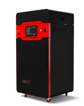
Although the core technology is the same, there are subtle but significant differences between preparing files for desktop SLS systems like the Sinterit LISA X, and for industrial printers from EOS or 3D Systems.
Industrial machines can handle larger and more detailed files, but they also demand cleaner meshes and higher precision in design tolerances. A poorly prepared model may lead to failed prints costing hundreds in materials and machine time.
Desktop systems are more forgiving but still benefit from streamlined files. Since their build volumes are smaller, it may be necessary to break down large assemblies into modular parts. In both cases, hollowing out models and adding escape holes for powder removal is recommended.
| Feature | Industrial SLS (EOS, 3D Systems) | Desktop SLS (Sinterit, Formlabs Fuse) |
|---|---|---|
| Resolution | Higher (up to 60 μm) | Moderate (75 – 110 μm) |
| Tolerance | ±0.2 mm | ±0.3 – 0.5 mm |
| File size | Large assemblies | Smaller, modular parts |
| File format | STL / AMF / 3MF | STL / 3MF |
| Nesting tools | Automated & optimized | Often manual or semi-auto |
| Post-processing | Automated depowdering | Manual depowdering |
FAQ: 3D printing files for SLS
STL is the most common and widely supported, but if you need to include metadata, part relationships, or printer settings, 3MF is a better option. For highly detailed industrial applications, AMF can offer even more flexibility.
Technically, yes — but you may run into issues with wall thickness, unsupported details, or incorrect orientation assumptions. FDM models often rely on support structures, which SLS doesn’t use, so redesigning or adapting the file is often necessary.
Use mesh analysis tools like Netfabb, Meshmixer, or Magics. They can identify holes, non-manifold edges, and self-intersecting geometry. A manifold model is crucial for reliable SLS prints.
Typically, 0.7 mm is the absolute minimum for fine features. For structural components, 1.0 – 1.2 mm is safer, especially if the part will undergo mechanical stress or aggressive post-processing.
Use internal hollowing tools in your CAD software and always include powder escape holes — preferably at low points where powder naturally accumulates. Two or more holes are usually sufficient for most parts.
Likely due to insufficient clearance. For moving parts, design a gap of at least 0.2 mm between components. For tighter tolerances or long prints, increase this to 0.3–0.5 mm to account for thermal expansion.
Absolutely. Poor nesting wastes build volume and material, increases print time, and may cause uneven cooling. In production scenarios, automated nesting tools can improve efficiency by 30% or more.
Not really. STL is mesh-based and doesn’t preserve parametric features or design history. For serious design changes, work with the original CAD files (e.g. STEP, IGES) whenever possible.
Use your CAD software to segment the model at logical joining points. Consider using alignment keys or interlocking joints, and keep in mind powder removal for each segment.
Conclusion: better files, better prints
In SLS 3D printing, file preparation is not an afterthought — it’s a critical success factor. From choosing the right format and verifying geometry, to optimizing orientation and nesting, every step plays a role in the outcome of your print.
Whether you’re producing prototypes or end-use parts, mastering SLS file preparation will save you time, materials, and frustration. With the right tools and knowledge, your 3D printer becomes more than just a machine — it becomes a reliable production partner.