How to get the most out of the surface finishing in 3D printing with AMT & Sinterit
Vapour smoothing is an incredible post-processing for SLS-printed parts that elevates surface quality, reduces porosity, and delivers an overall stronger, more injection-moulded aesthetic. While many articles (including our own) outline the high-level benefits of vapour smoothing, this follow-up guide focuses squarely on how to smooth 3D printed parts to maximise results when using Additive Manufacturing Technologies (AMT)’s vapour smoothing systems in conjunction with Sinterit’s SLS powders. We’ll cover how to design parts for optimum smoothing, avoid classic mistakes in the smoothing cycle, and understand which geometries or features present inherent challenges.
Design rules for better surface finishing results
Before sending parts into an AMT SFX machine (configured with Sinterit-specific profiles), it’s crucial to optimise your CAD design so that the vapour can interact uniformly with every surface and avoid post-cycle surprises. Below are five key considerations:
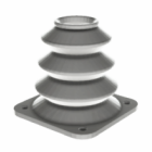
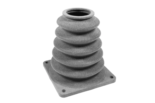
1. Maintain uniform wall thickness
AMT’s profiles assume consistent thermal and solvent diffusion. When wall thickness varies—say, from 1.0 mm up to 5.0 mm—thinner areas may overheat or warp before thicker sections begin to smooth. Vapour smoothing the models of various wall thicknesses might lead to some parts undersmoothing and some oversmoothing. Of course, some variations won’t hurt, so for example, having walls that are in the range of 8.0 to 12.0 mm should work very nicely. To get the best results, try keeping to uniform wall thickness across the model.

When the average wall thickness is set for the thickest wall, the thinnest ones might get over-smoothed or warped.
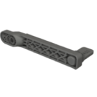
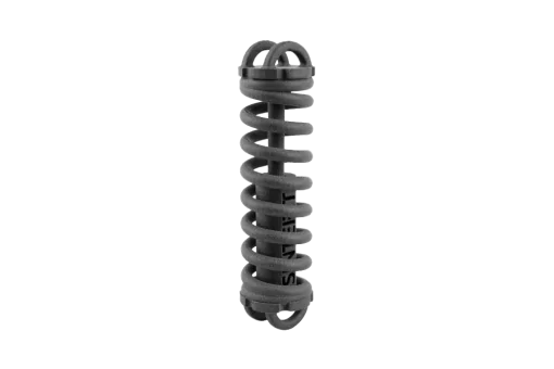
2. Keep mesh density moderate
Lattice structures go hand in hand with SLS thanks to the nearly isotropic properties of the printouts made with it. These meshes can be further enhanced with the introduction of vapour smoothing, which can strengthen smaller parts. That being said, lattice structures have to follow the same rules as the entire model — keeping the lattice structure thickness in line with the average wall thickness of the model will help guarantee great results after the smoothing process. In our testing, however, we were able to successfully postprocess very thin structures, so testing is recommended.

Although it might not be perfectly visible in the picture, the very thin mesh (0.75mm) gets a bit warped.
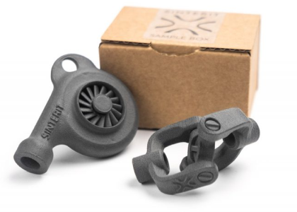
3. Anticipate thread shrinkage
Threads are an inseparable part of a water- and air-tight container that work great after vapour smoothing. Solvent exposure will, however, tend to “pull” or “round off” sharp thread crests. This might influence the end part being too loose, which in turn will compromise the seal. The inner diameter of the threaded parts is also very important; thread on a 5.0 mm thick tube wall will require more aggressive smoothing than the one on a 2.0 mm thick tube wall, even if the external diameter of the tube stays the same, because vapour smoothing settings are wall thickness dependent. The best course of action is to print a small thread coupon and run a single smoothing cycle to determine exact shrinkage, then update your model.

Threads can shrink during the smoohting process, the issue is solved in the second iteration.
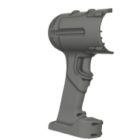
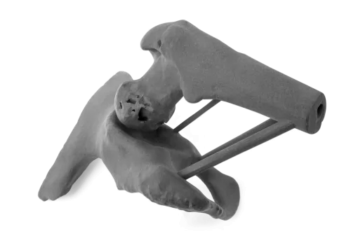
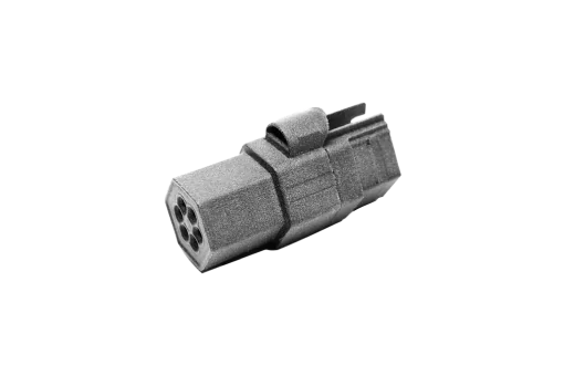
4. Account for semi-enclosed or hollow sections
Vapour cannot penetrate fully into narrow tubes, deep cavities, or very tight fins, especially if the opening is facin down. Alternatively if the opening is facing up, the solvent might pool inside an enclosed cavity, it can lead to excessive local melting or film of melted material forming. Whenever possible, add drain holes or venting channels to allow solvent vapours to circulate through and escape. Remember that “cups” tend to cause pooling when facing up or undersmoothing when facing down.

The solvent will have a hard time reaching the deep, narrow cavities on the underside of the model.
Common surface finishing mistakes and how to avoid them
Even with a well-designed part, inexperience or omission of key process checks can lead to avoidable defects. Here are the most common pitfalls:
1. Under- or over-smoothing
This is probably the most common mistake during the vapour smoothing process — selection of the wrong presets. There are three main settings you need to dial in before the print process: the average wall thickness, the chamber utilisation and smoothing level. Selecting too thin average wall thickness or too low chamber utilisation will result in an under-smoothed model — the surface might not be smoothen and still porous, and a white deposit can be seen on the surface of the model. Selecting too high average wall thickness or too high chamber utilisation will result in over-smoothed models — the edges will not be sharply defined, the fonts might look melty, and some delamination might occur.
To avoid this issue:
- Always make sure to select the right average wall thickness — you can use CAD software if you don’t know what the average wall thickness is.
- Make sure that you’ve selected the right chamber utilisation — the values 25%, 50%, 75%, and 100% should roughly reflect the volume of the chamber occupied by the models, while oversized is reserved for singular extra-large models.

From the left: undersmoothen model, correctly processed, oversmoothen model.
2. Solvent pooling
Pooling of the solvent on the models might lead to some defects on the surface of the models that will influence the overall look of the models. This too might be caused but the usage of too aggressive vapour smoothing settings. Pooling is an issue that can be eliminated by some changes in the design (namely by avoidance of very sharp edges, but the best way to tackle this defect is simply the right arrangement of the printout in the vapour-smoothing chamber. Think where the drops might pool on the surface and arrange the model in a fashion that makes the big flat surfaces parallel to the rack, or make the excess easy to drip from the surface.

Left: model hanged vertically, right: model hanged hoizontally.
3. Incorrect part placement: rack vs. hanging
Generally speaking, the models should be hung from the racks during the smoothing, but for some models and geometries, this might be difficult. Laying the parts on the racks using spikes, which would leave only tiny marks on models or smoothed parts of the models that are to be removed after the process is done, might help, but keep in mind that the models might “melt” into the rack during the smoothing process.

Right: model hanged, left: model placed on the rack.
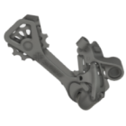
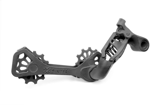
4. Overpopulating the chamber and fusion between the parts and the movable parts
During the vapour smoothing process, the models get dissolved on the surface, which might result in fusing with each other. The same is true for movable parts, which might result in fused mechanisms. Spacing between the models is therefore very important. It’s not impossible, however, to print movable parts; the fusion is only on the surface, so it’s possible to break the parts free if the area of contact is small, like in the chain.

Left: after smoothing, right: after separating links.
Limitations of smoothing based on geometry and material
Although vapour smoothing can give you amazing results by improving the surface finish, like with everything, the better the models you put through the process, the better results you will get at the end. And vice versa – if you put poor quality models (incorrect positioning during printing or poor quality material), despite the magic of vapour smoothing, certain issues cannot be fully “fixed” in post. The three main issues that will be carried over are orange peel (caused by poor powder quality or tempering with printing settings), fractures of models (caused by impact) and the layser lines (caused by incorrect arrangement of models in the print area).

Left: model printed correctly, Right: model printed at a shallow angle with visible layer lines.
Conclusion: smarter surface finishing in SLS 3D printing
By integrating these design guidelines and process-level insights, you can leverage AMT’s PostPro SFX vapour smoothing machines — tuned with Sinterit’s powder-specific recipes — to achieve truly exceptional SLS finishes. Whether you’re producing PA11 CF end-use components, PA12 Industrial prototypes, or Polypropylene chemically resistant tools, following these techniques will minimise trial-and-error, reduce scrap, and result in parts that look and feel almost as good as traditional injection-moulded counterparts for a fraction of the cost.
Stay tuned for our follow-up article on “How to Estimate & Control Vapour Smoothing Costs,” where we’ll break down machine cycle times, solvent usage, labour, and per-part cost calculators. In the meantime, if you have questions about setting up an AMT + Sinterit workflow, contact our application specialists to schedule a trial, receive custom machine profiles, or arrange a site visit.
FAQ: how to smooth 3D printed parts and optimize finishing
Stiff materials like PA12 Industrial, PA11 CF or Polypropylene would work the best with vapour smoothing. Processing TPU materials like Flexa Performance is tricky and has more limitations, but is still possible.
The maximum size of the smoothed part is only limited by the chamber size. As for the smallest parts — if the features are very thin (<2mm) they might be hard to smooth or get fused with surrounding material.
Yes, but there are some limitations – the uniformity of the parts is the key,
As all the defects of the models will be carried over to smoothed part, precise sandblasting is highly recommended. No need to use water or alcohol though.
Threads will shrink, so you need to tak this into consideration during the design process. Moving parts might fuse stuck however if only small parts of the moving elements are touching together they might be possible to separate or break apart after smoothing.
Make sure that the parts are not touching each other or the racks. Inside the chamber, there is a fan that helps the solvent circulate, so give the models a bit of “wiggle room”.
Make sure that the settings for material, average wall thickness, chamber utilisation and smoothing level are set correctly. Use models that are printed correctly. Arrange the models on the racks so they are not touching each other or the surface of the racks.