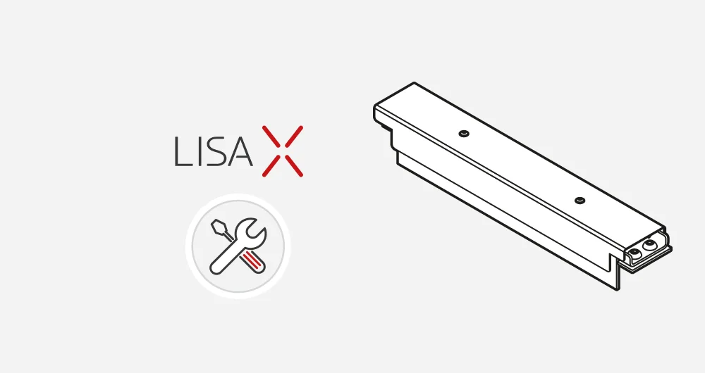
Recoater blade kit
ASSEMBLY MANUAL
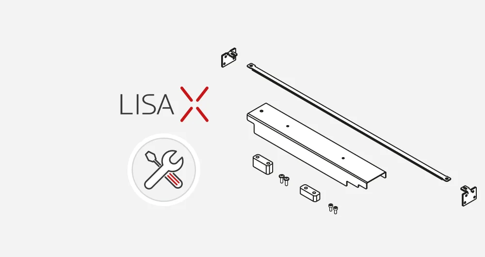
LIST OF ELEMENTS:
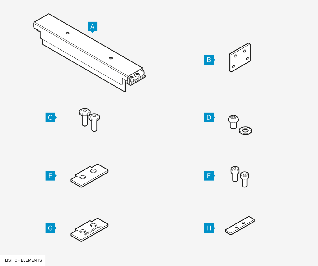
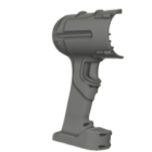
- Recaoter blade without cover 1 pc
- Metal cap 2 pcs
- M3x8 black screws* 2 pcs
- M6x10 screws with serrated washer* 2 pcs
- Linear bearing washer I (SB016251A) 1 pc
- M3x6 screws with cylindrical head* 10 pcs
- Linear bearing washer II (SB013196A) 1 pc
- Levelling slider washer (SB016250A) 1 pc
* The amount of screws in the kit may be more than the installation assumes. This is a spare.
- You will need:
- • Allen key 2.0, 2.5, 4.0 mm
- • Brush or compressed air
- • Box or zip-lock bag for part
1.1 Installing Recoater blade
- Prepare an appropriately sized box or ziplock bag to store all replaced items.
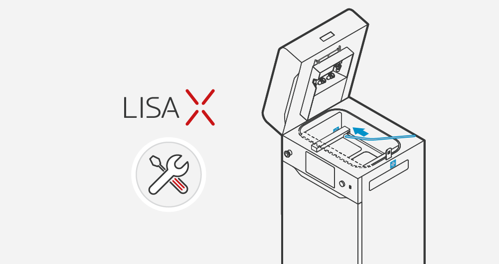
- Choose UNLOCK LID on the screen.
- Push on the lid and pull it up using the lid handle. Remember, you only have 10 seconds to open it before the lock activates again.
- Clean the print chamber if needed.
- Go to the MAINTENANCE and then the CONTROL PANEL tab.
- Use the steering arrows to position the Recoater in between the Beds.
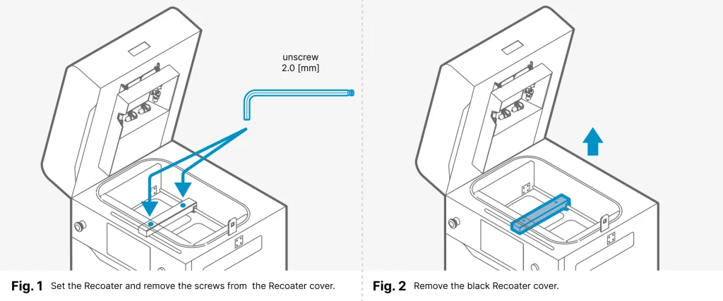
- Using a 2 mm allen key, unscrew both screws on the Recoater cover (fig. 1).
- Gently remove the black cover from the Recoater and put it away for later (fig. 2).
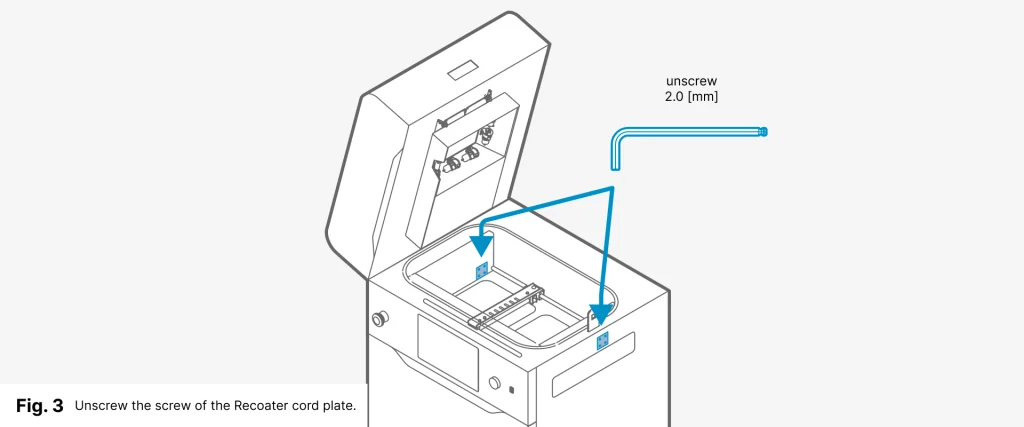
- Using a 2 mm (Recoater cord) or a 2.5 mm (Recoater strip) allen key, unscrew the screws on the Recoater cord mounting plate on the left and right sides (fig. 3).
- Fit metal caps in the side holes. Use eight M3x6 screws (four per side) and allen key 2.5 mm.
TIP: If you do not have enough space, move the Recoater using the steering arrows on the control panel (MAINTENANCE/CONTROL PANEL).
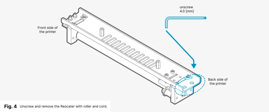
- Using a 4 mm allen key unscrew the two screws holding the Recoater to the bearing (fig. 4).
- Take out the Recoater with the cord (and optionally metal spacer if it is).
- Stow everything in the box/ziplock bag along with the screws.
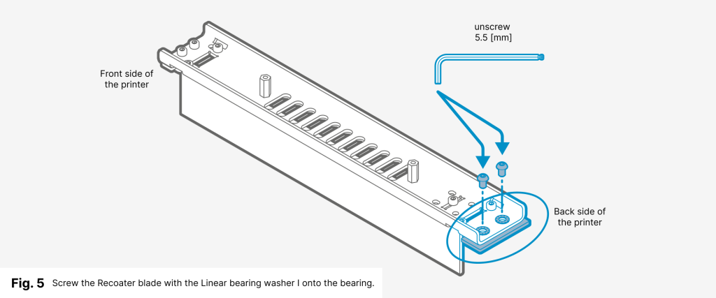
- Place the Linear bearing washer I (without the number stamped) on the bearing.
- Remove from the box: the Recoater blade and two M6x10 screws with the serrated washers.
- Position the Recoater blade correctly on the bearing and screw it together using a 4 mm allen key (fig. 5).
- Assess the gap between the Recoater blade and the print chamber. The correct value should be between 0.8 and 1.8 mm (fig. 6).
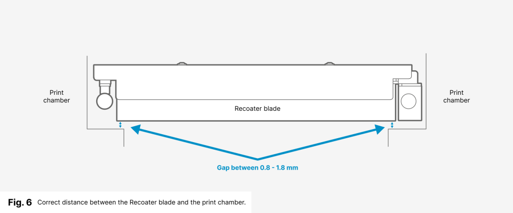
- If the gap is insufficient (less than 0.8 mm), use additional washers (Linear bearing washer II and Levelling slider washer).
- Unscrew the Recoater blade and use washers.
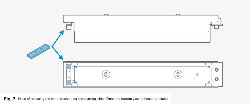
a. Levelling slider washer – Using the 2.5 mm allen key unscrew the Levelling slider (left side of the Recoater blade). Replace the metal washer (1mm) with the additional one from the set (2mm) and screw everything together (fig. 7).
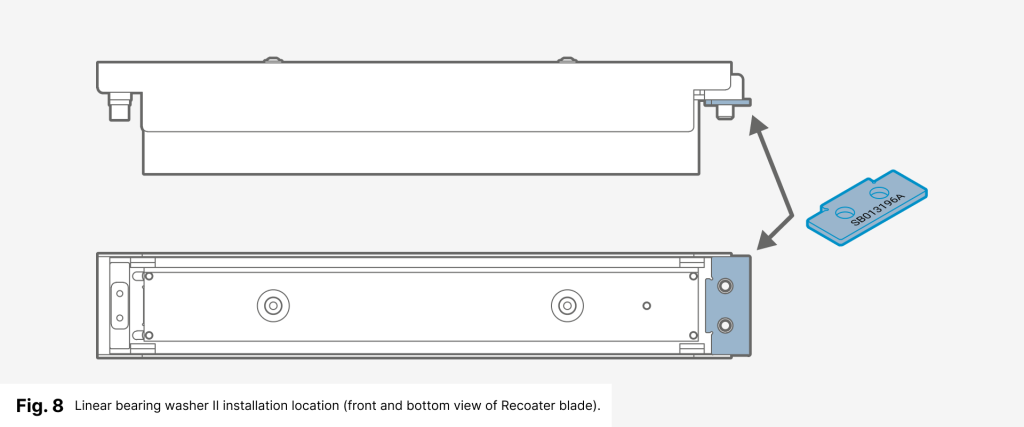
- Linear bearing washer II – Place an additional washer (with a stamped number) between the Linear bearing washer and the Recoater Blade (right side). Fasten everything with two M6x10 screws with the serrated washers (fig. 8).
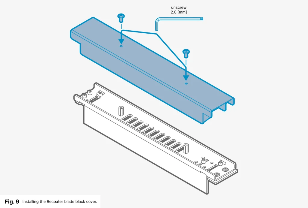
- Using a 2 mm Allen key and two M3x8 screws, fasten the black cover onto the Recoater (fig. 9).
1.2 Software activation on the printer
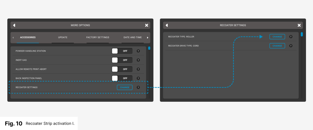
- On the screen under SETTINGS, select the MORE OPTIONS
tab and then RECOATER SETTINGS (fig. 10). - Press the CHANGE button and the next window will appear.
- Select the RECOATER DRIVE TYPE line and press the CHANGE button (fig. 10).
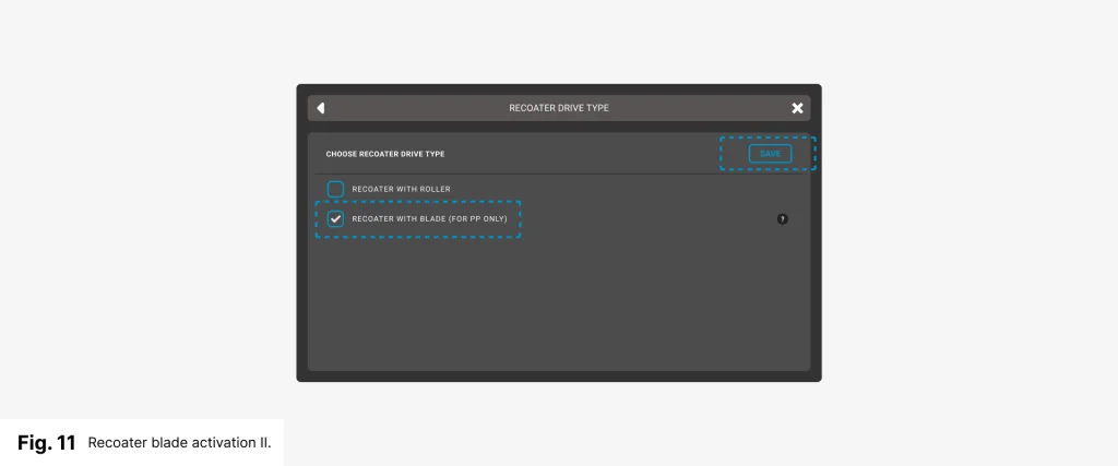
- Select the RECOATER WITH BLADE checkbox (fig. 11).
- Read the message carefully then click on GOT IT and SAVE.
- Now you can print using the Recoater blade.