Recoater strip retrofit
Assembly manual
LIST OF ELEMENTS:
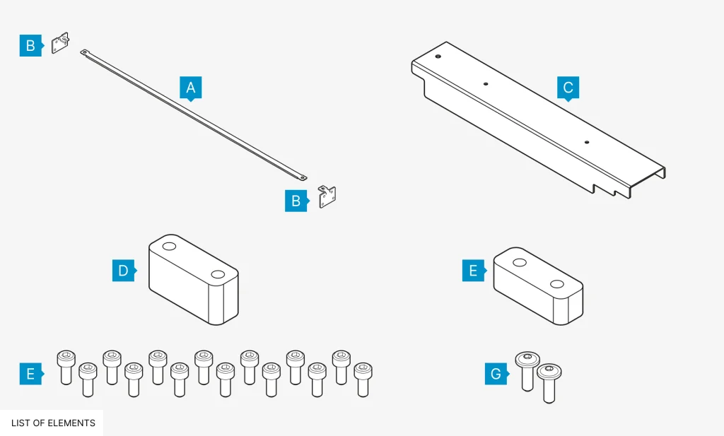
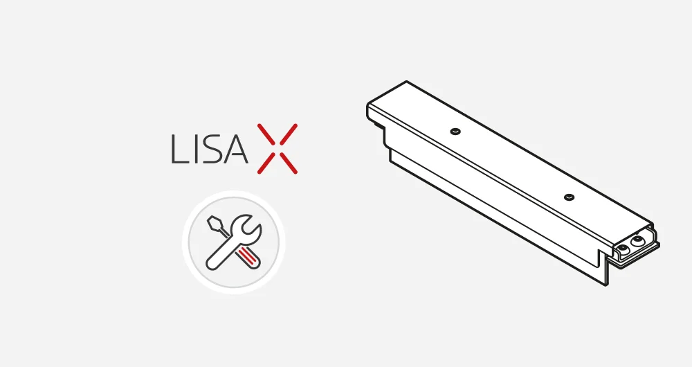
- Recoater strip 1 pc
- Angle brakets 2 pcs
- Black cover 1 pc
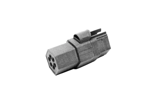
- Driver slider 1 pc
- Levelling slider * 1 pc
- M3x6 screws 14 pcs
- M3x8 black screws 2 pcs
* If the Recoater already has a replacement tribotape for the Levelling slider, it is unnecessary to replace it with the one included in the kit.
- You will need:
- • Allen key 2.0, 2.5, 3.0, 4.0 mm
- • Wrench/socket wrench 5.5 mm
- • Brush or compressed air
1.1 ADAPTATION OF THE RECOATER
- Choose UNLOCK LID on the screen.
- Push on the lid and pull it up using the lid handle. Remember, you only have 10 seconds to open it before the lock activates again.
- Clean the print chamber if needed.
- Go to the MAINTENANCE and then the CONTROL PANEL tab.
- Use the steering arrows to position the Recoater in between the Beds.
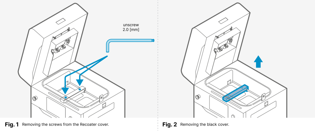
- Using a 2 mm allen key, unscrew both screws on the Recoater cover (fig. 1).
- Gently remove the black cover from the Recoater (fig. 2).
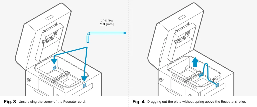
- Using a 2 mm allen key, unscrew the screws on the Recoater cord mounting plate on the left and right sides (fig. 3).
- Grab the cord from both sides and remove it from the knurled roller wheel.
- Drag out the end of the cord (without spring) above the Recoater’s roller. At first the mounting plate, then the ending, through the gap between the rotary shaft and Recoater housing. Be careful not to touch the roller (fig. 4).
- Remove the second plate (with spring) from the socket.
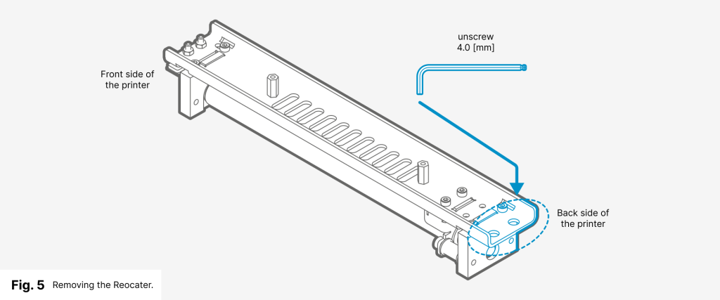
- Using a 4 mm allen key unscrew the two screws holding the Recoater to the bearing (fig. 5).
- Take out the Recoater. Set the metal spacer aside.
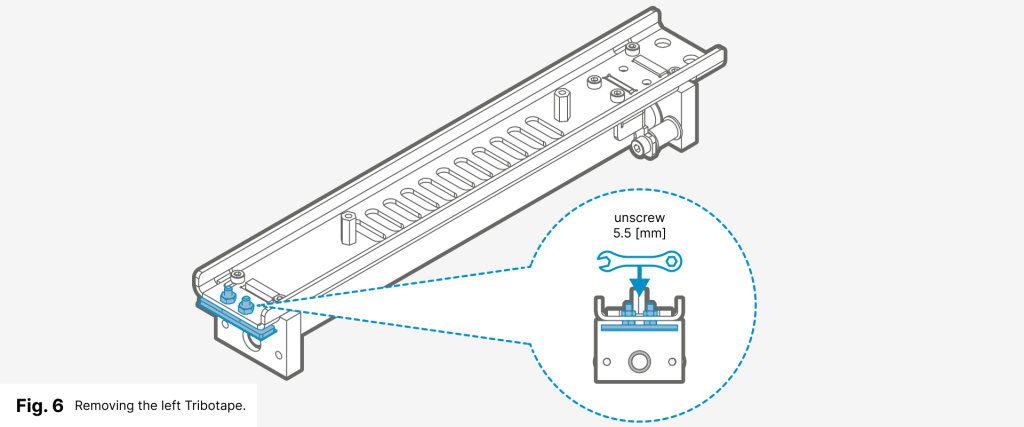
- Using a 5.5 mm wrench loosen the two screws of the Tribotape on the left side of the Recoater (fig. 6).
- Remove the Tribotape (fig. 6).
- Clean the surface of the Recoater (Isopropyl alcohol or vacuum cleaner).
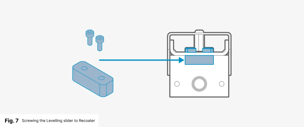
- Screw the Levelling slider in place of the Tribotape. Use the two M3x6mm screws from the supplied kit and the 2.5 mm allen key (fig. 7).
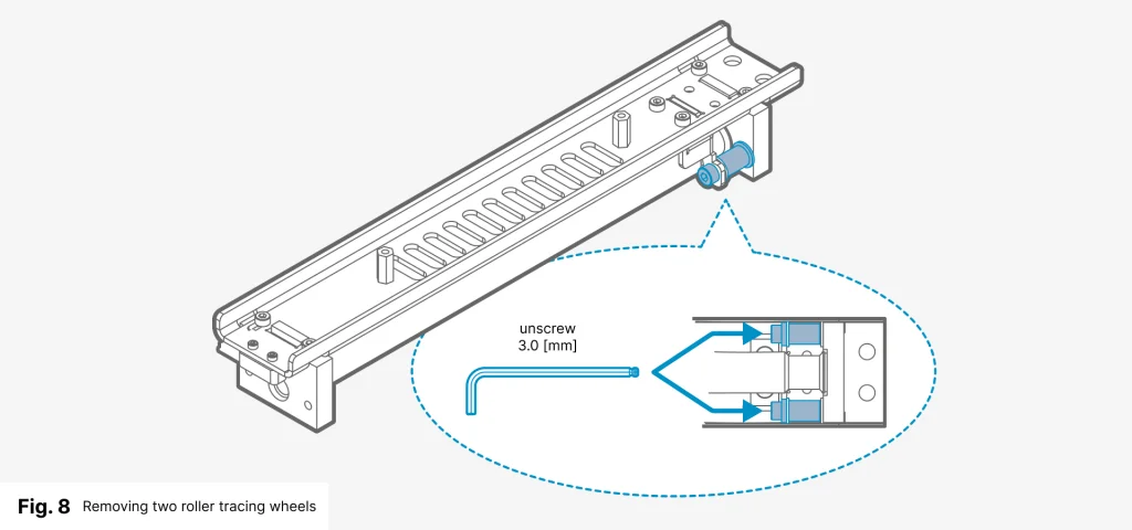
- Using the 3 mm allen key unscrew the two roller tracing wheels for the drive cord (fig. 8).
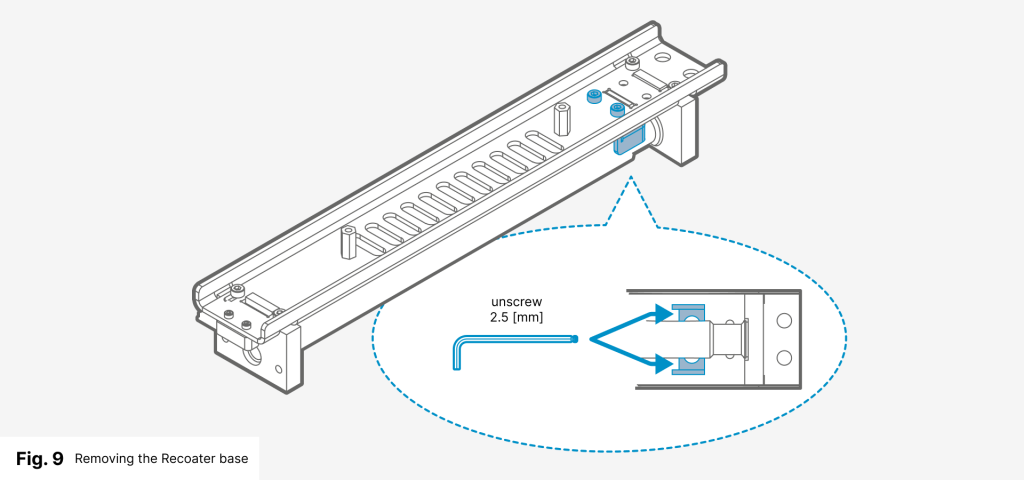
- Using a 2.5 mm allen key loosen the two screws of the Recoater base on the right side of the Recoater (fig. 9) and remove it.
- Clean the surface of the Recoater (alcohol or vacuum cleaner).
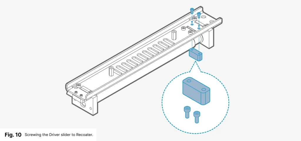
- Screw the Driver slider into the recess, above the knurled roller. Use the two M3x6mm screws from the supplied kit and the 2.5 mm allen key (fig. 10).
- Place a metal spacer on the Recoater bearing and then reassemble the Recoater.
- Using a 4 mm allen key and two M6x10 screws with a serrated washer, screw the Recoater onto the bearing.
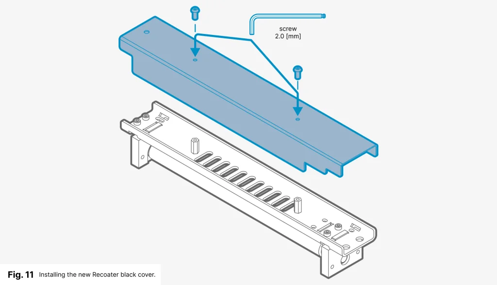
- Using a 2 mm allen key and two M3x8 screws, fasten the black cover onto the Recoater (fig. 11).
1.2. RECOATER STRIP INSTALLATION
- Take the two angle brackets holding the Recoater slider out of the box.
- Screw the two angle brackets in place of the previous plates (fig. 12). Use four M3x6 screws per bracket and a 2.5 mm allen.
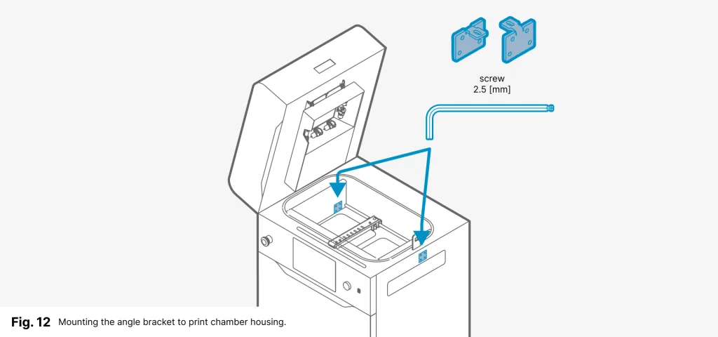
- If you do not have enough space, move the Recoater to the opposite side using the steering arrows on the screen.
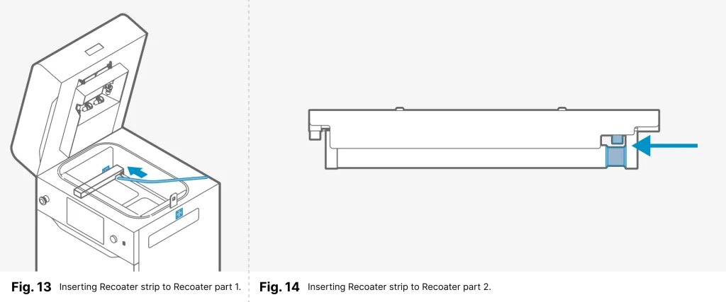
- Remove the Recoater strip from its packaging. Check that it is not damaged.
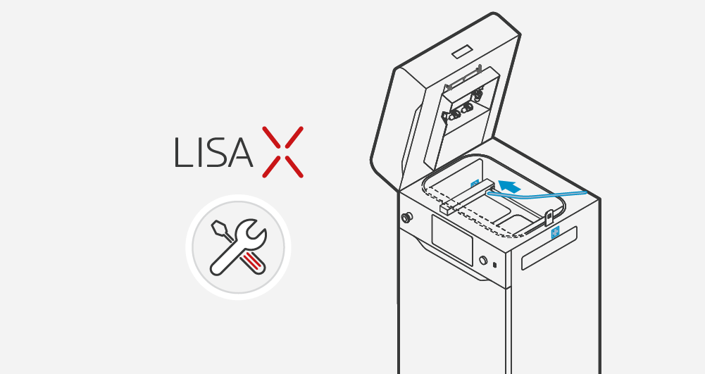
- Slide the Recoater strip into the gap between the knurled roller and the Driver slider (Fig 13 & 14). Don’t bend the strip too much – it might break!
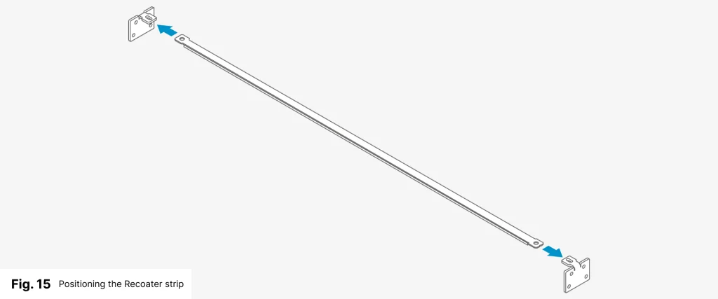
- Mount the end of the Recoater strip under the angle bracket (fig. 15).
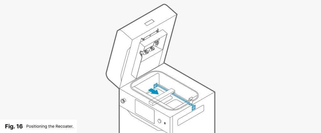
- While holding the Recoater strip, position the Recoater in the middle, between the beds (fig. 16). Use one of the available ways:
- press POSITION RECOATER (option available during the Onboarding process);
- go to the MAINTENANCE menu, next to the CONTROL PANEL tab and control with the steerings arrows.
- Similarly, position the second end of the Recoater strip to the angle bracket.
- Using a 2.5 mm allen key and two Mx6 screws, pre-screw the Recoater strip onto the angles (fig. 17).
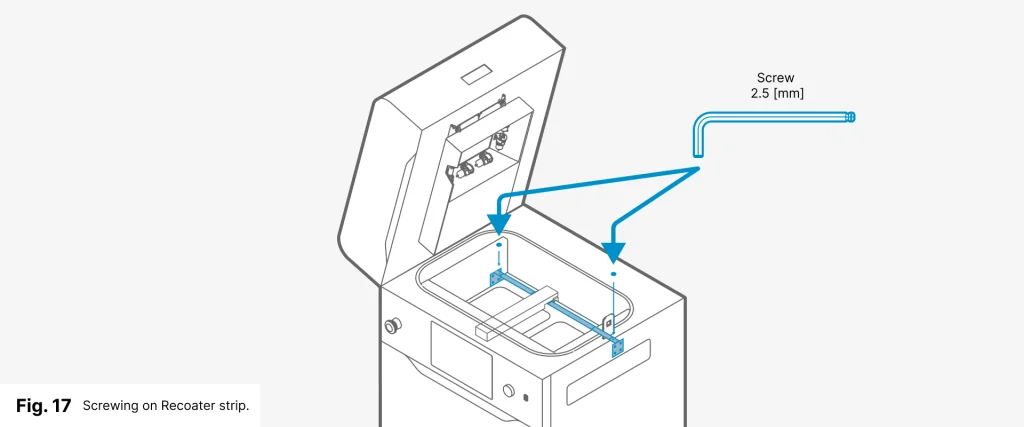
- Check that the Recoater strip does not bend and tighten the screws to the end.
- Using the steering arrows check that the Recoater moves smoothly along the Recoater strip.
1.3 SOFTWARE ACTIVATION ON THE PRINTER
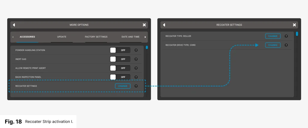
- On the screen under SETTINGS, select the MORE OPTIONS tab and then RECOATER SETTINGS (fig. 18).
- Press the CHANGE button and the next window will appear.
- Select the RECOATER DRIVE TYPE line and press the CHANGE button (fig. 18).
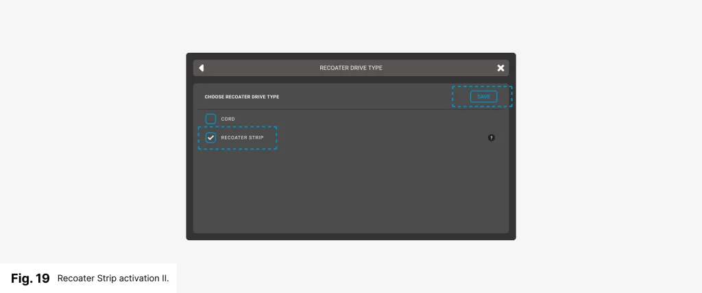
- Select the RECOATER STRIP checkbox (fig. 19).
- Read the message carefully then click on GOT IT and SAVE.
- Now you can print using the Recoater Strip.