Feeder clutch kit – PHS/Multi PHS
ASSEMBLY MANUAL
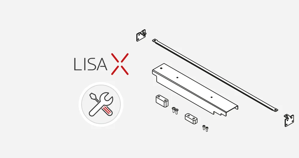
- To complete the assembly process, you will need:
- • Allen keys 5.0, 3.0, 2.5, 2.0 mm
- • Wrenches 17.0, 7.0 mm
- • Thread locker
- Disconnect the device from the power source.
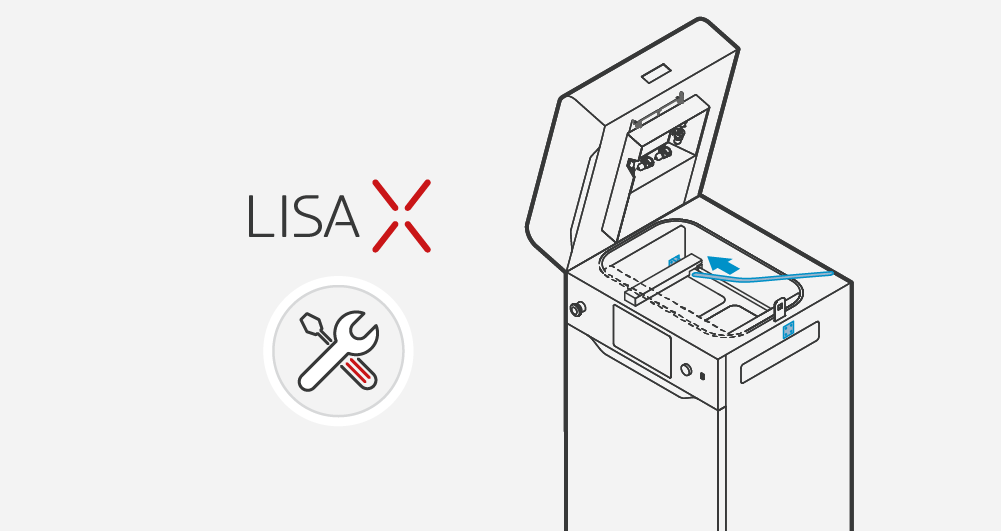
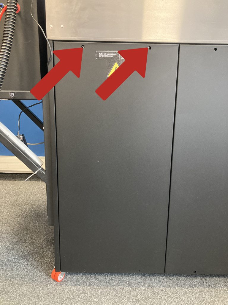
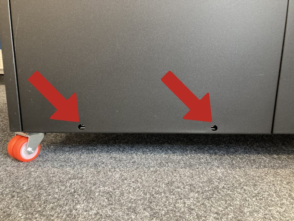
- Unscrew the four screws securing the left cover of the device with a 5 mm Allen key.
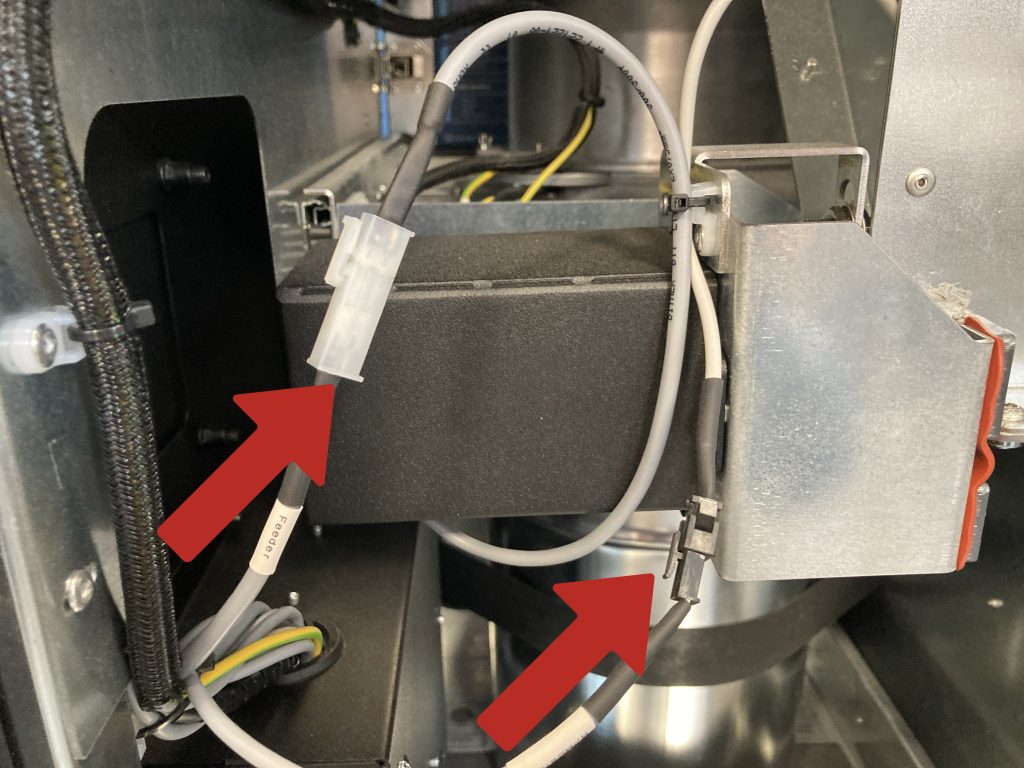
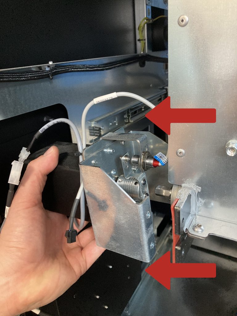
- Disconnect the feeder screw drive and Hall sensor cables.
- Unscrew the four motor mounting screws using a flat 7mm wrench.
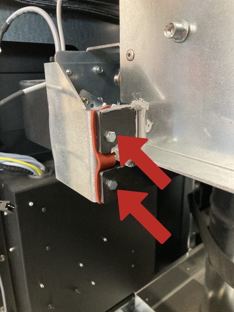
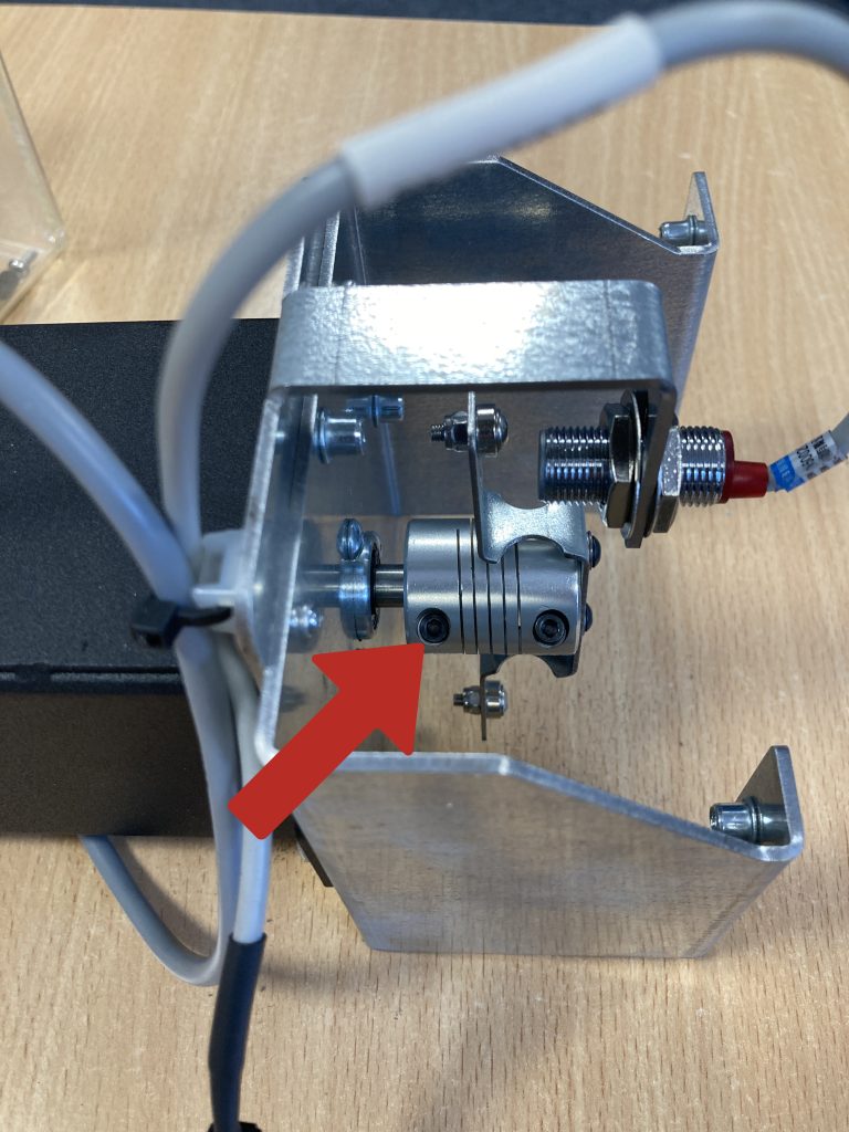
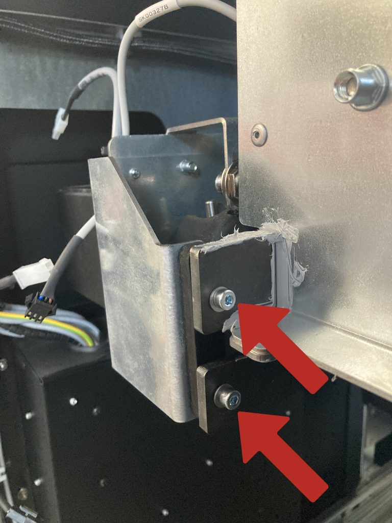
- Unscrew the screws on the clutch side using a 2.5 mm Allen key.
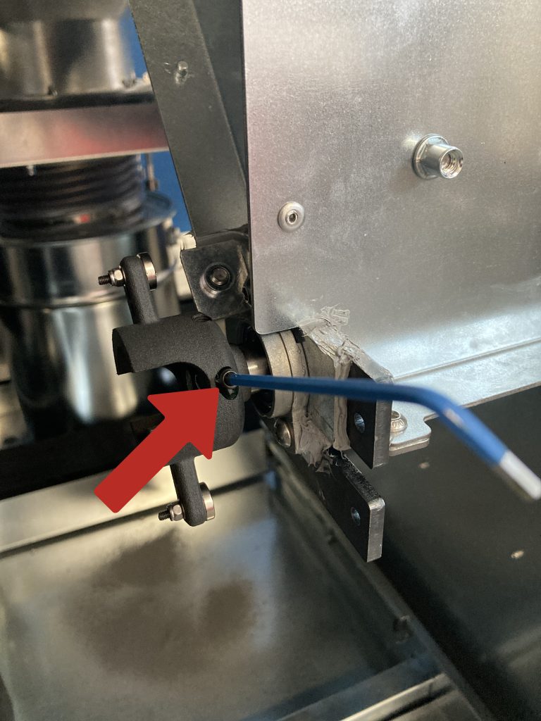
- Remove the tension screw on the clutch side using a 2 mm Allen key.
- Extract the motor along with its mounting from the device.
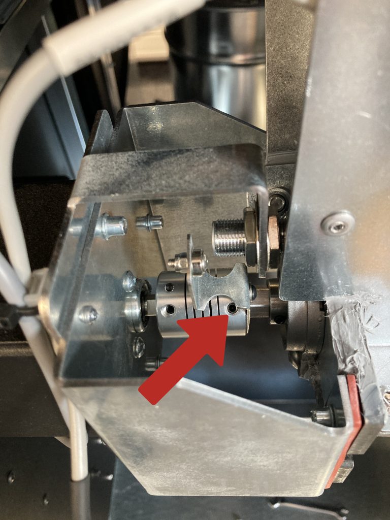
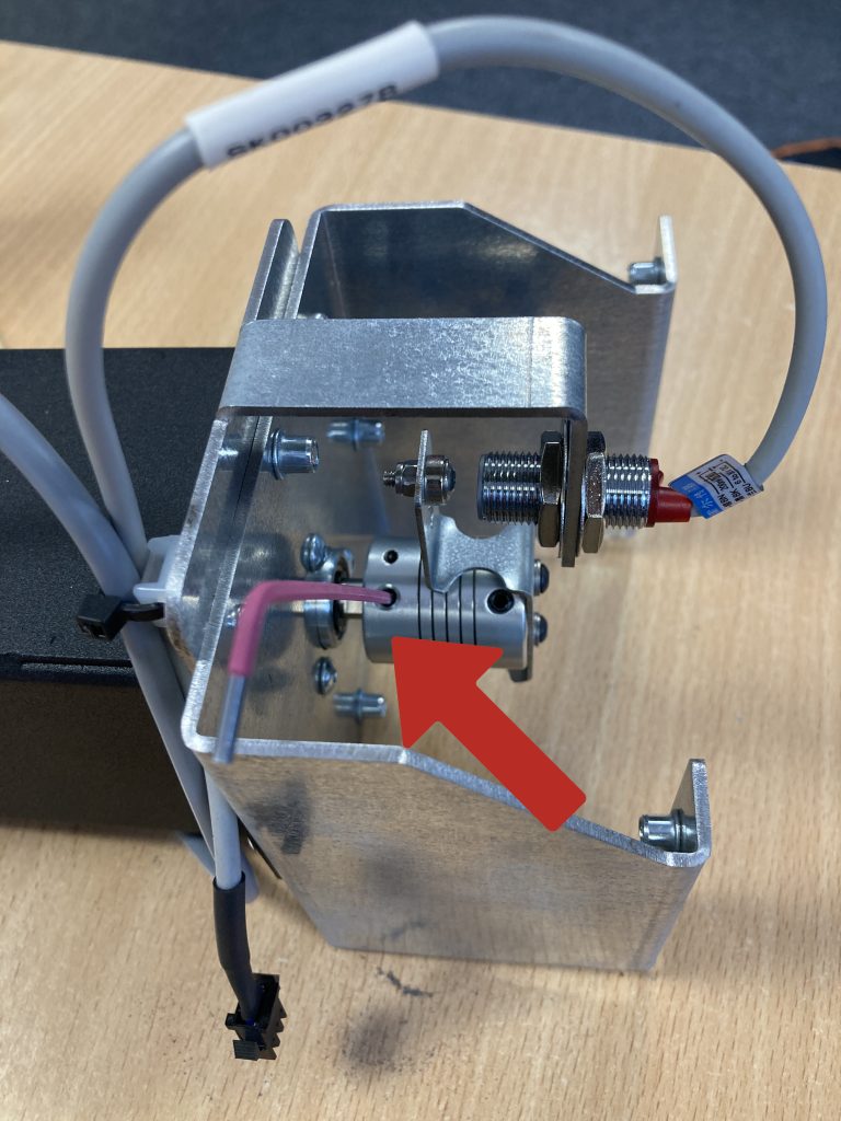
- Unscrew the tension screw on the motor side using a 2.5 mm Allen key.
- Unscrew the second tension screw on the motor side using a 2 mm Allen key.
- Remove the old clutch.
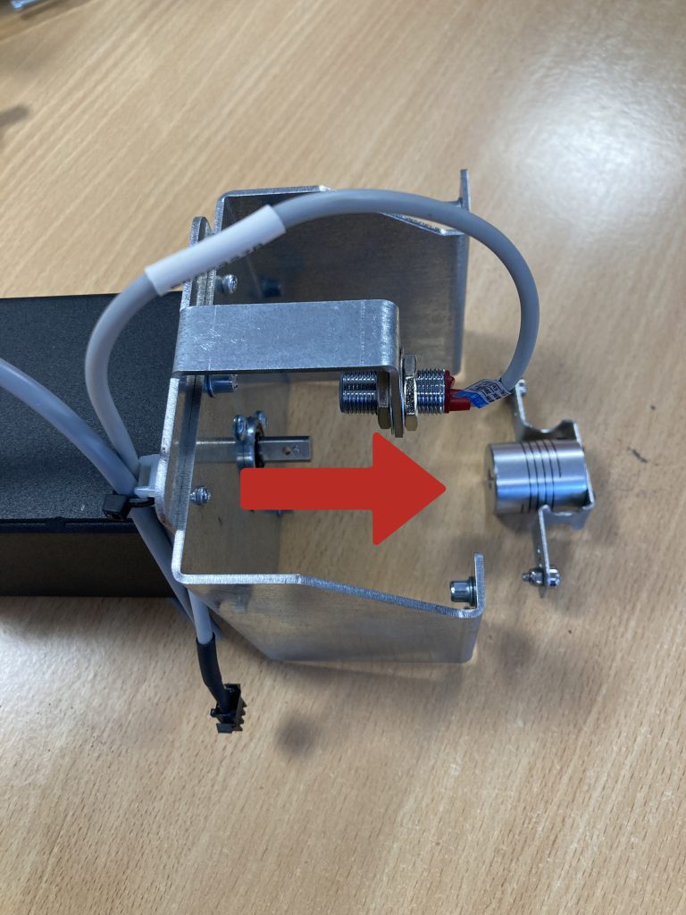
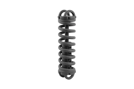
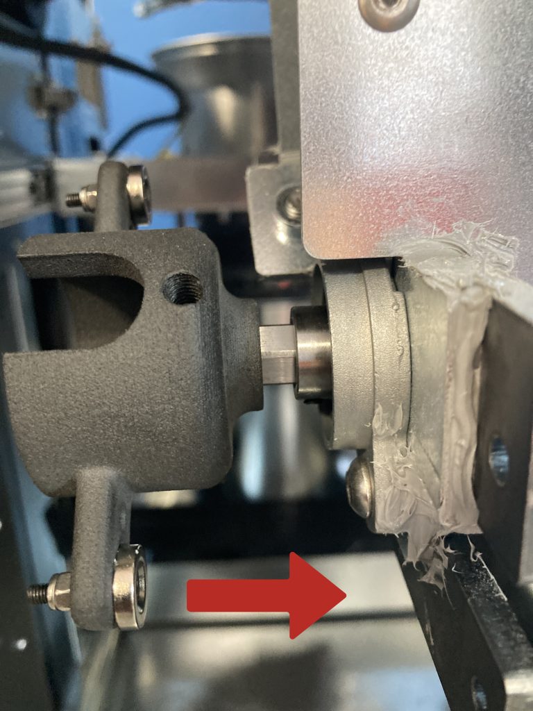
- Install the end of the new clutch onto the motor shaft.
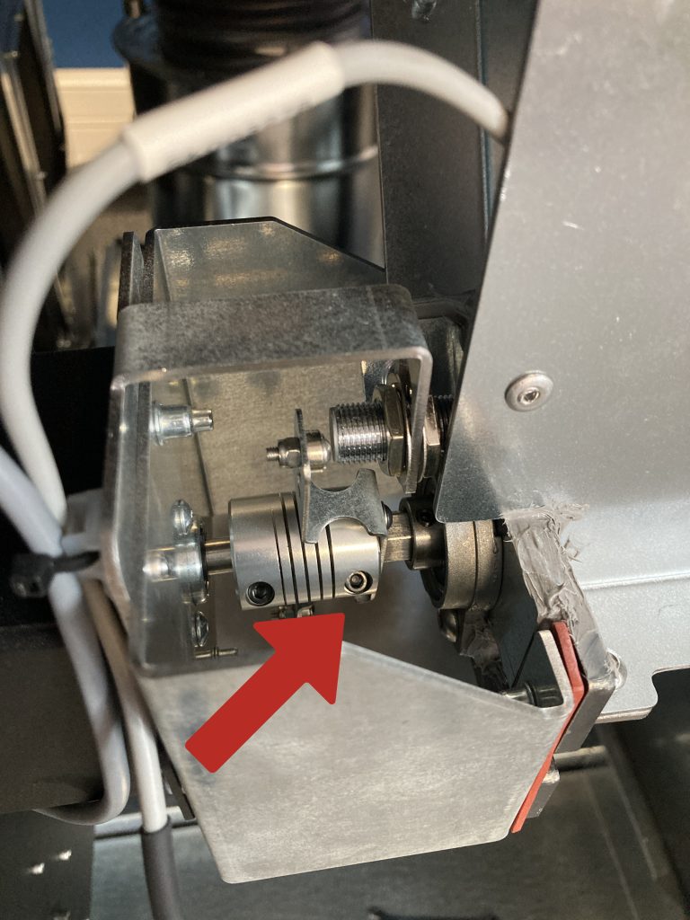
- Apply a drop of the thread locker to the set screws on the tensioning spirals.
- Screw in the tension screw using moderate force until a clear resistance is felt. Use a 3 mm Allen key.
- Repeat for the second tension screw.
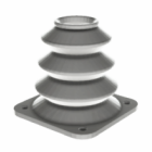
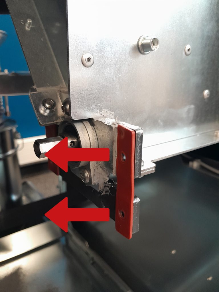
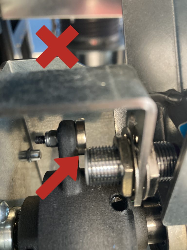
- Remove the old anti-vibration pads (red).
- Place the second part of the clutch onto the feeder screw, all the way to the end.
- Apply thread locker to the set screws on the tensioning spirals and tighten the clutch to the feeder screw using 4 tension screws.
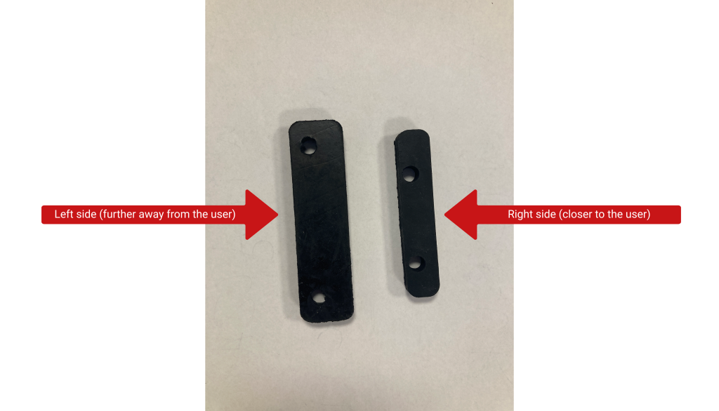
- Attach larger anti-vibration pads on the left side (far from the user) and smaller ones on the right side.
- Attach the motor mounting to the device with the appropriate side. Secure it with four new screws (3mm Allen wrench).
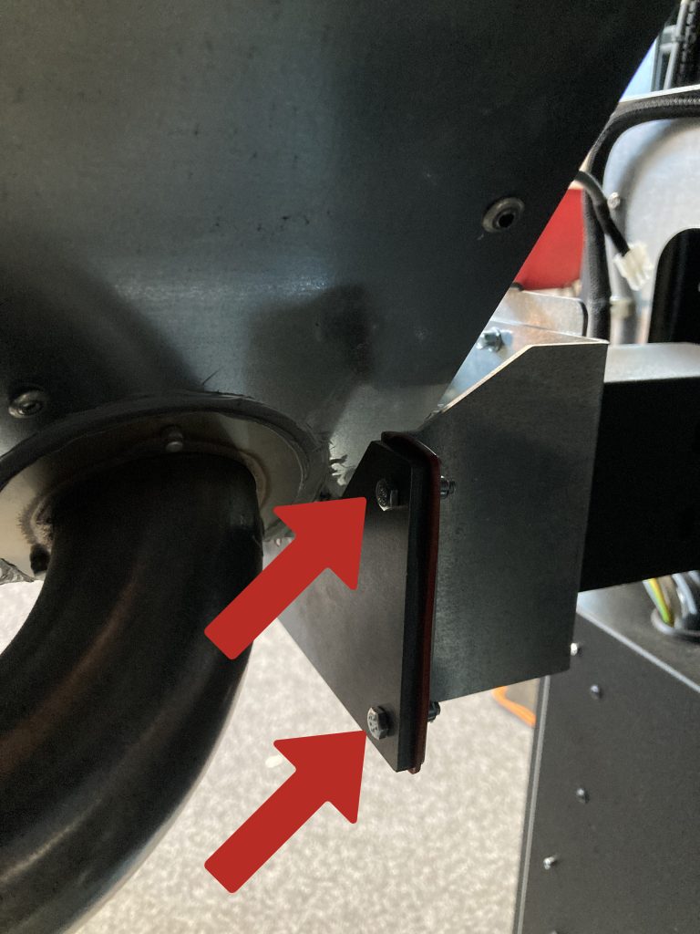
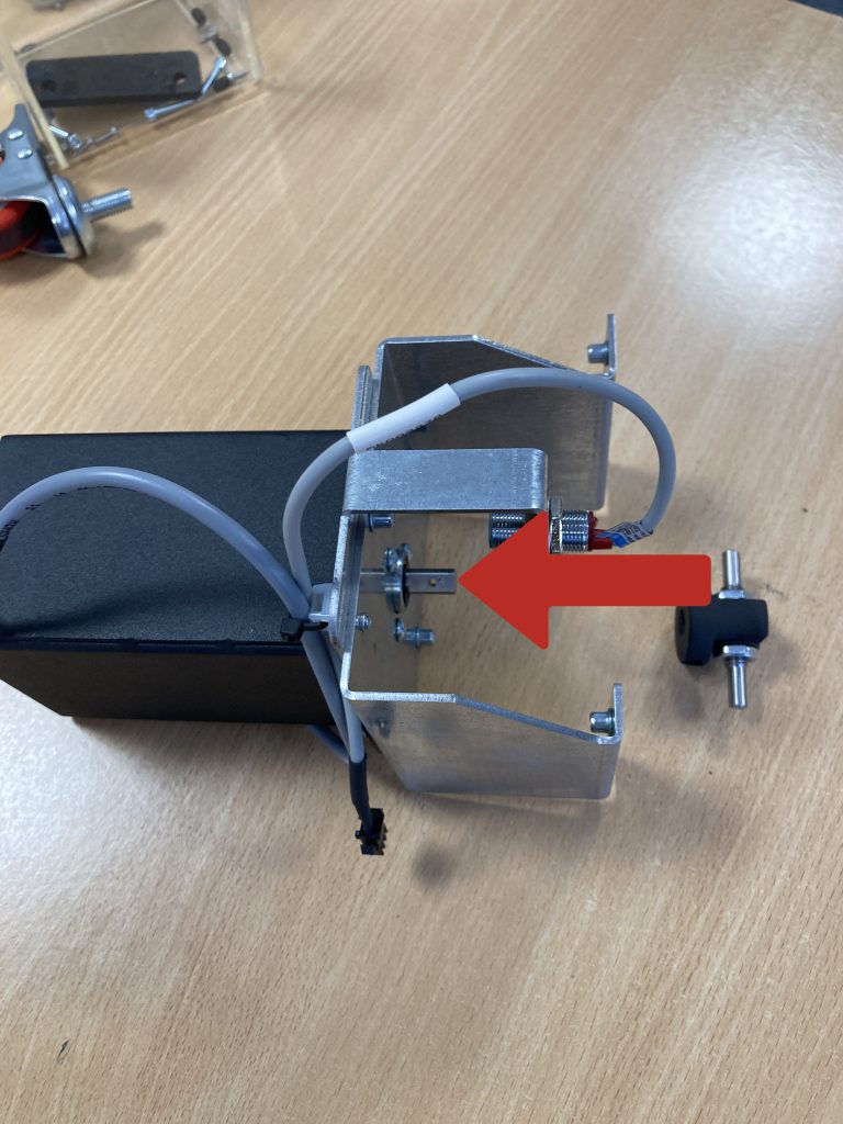
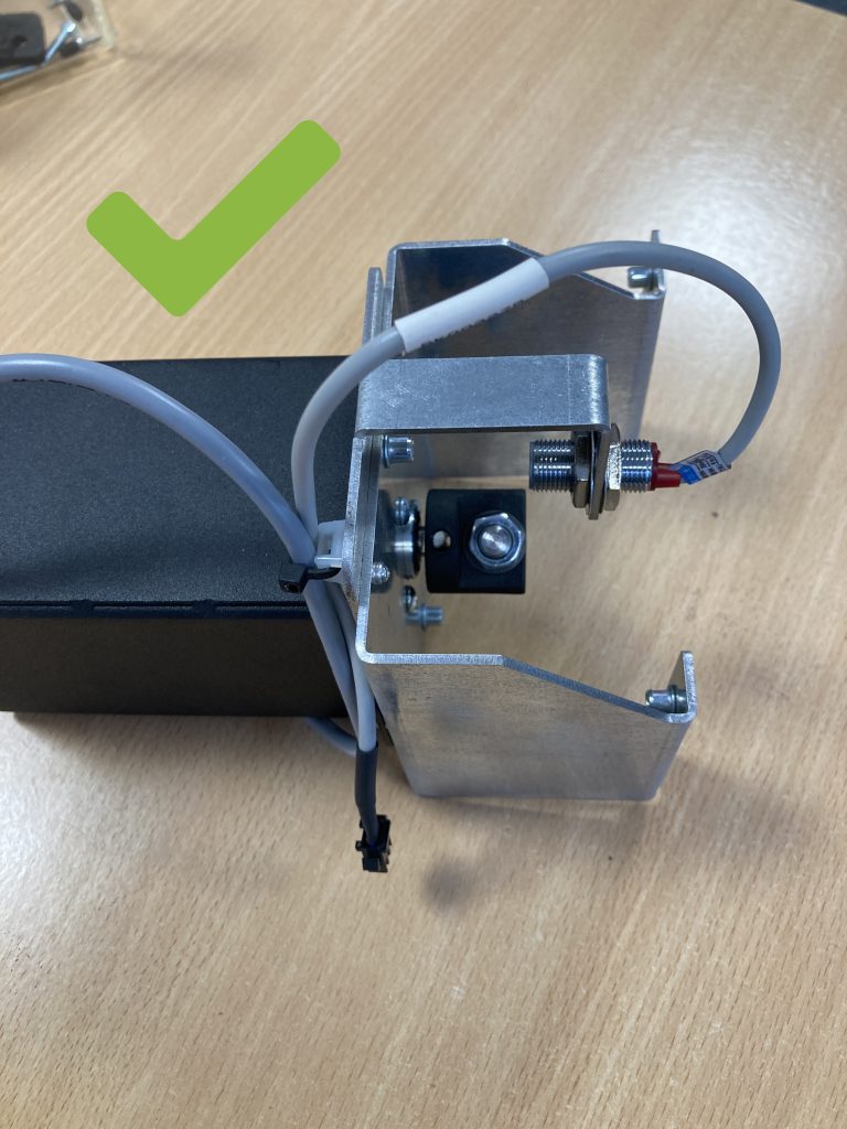
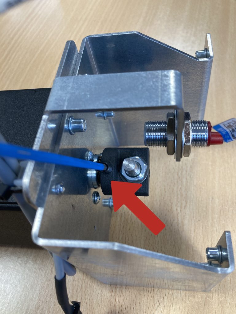
- Adjust the Hall sensor. Loosen the nuts securing the Hall sensor using a 17 mm flat wrench.
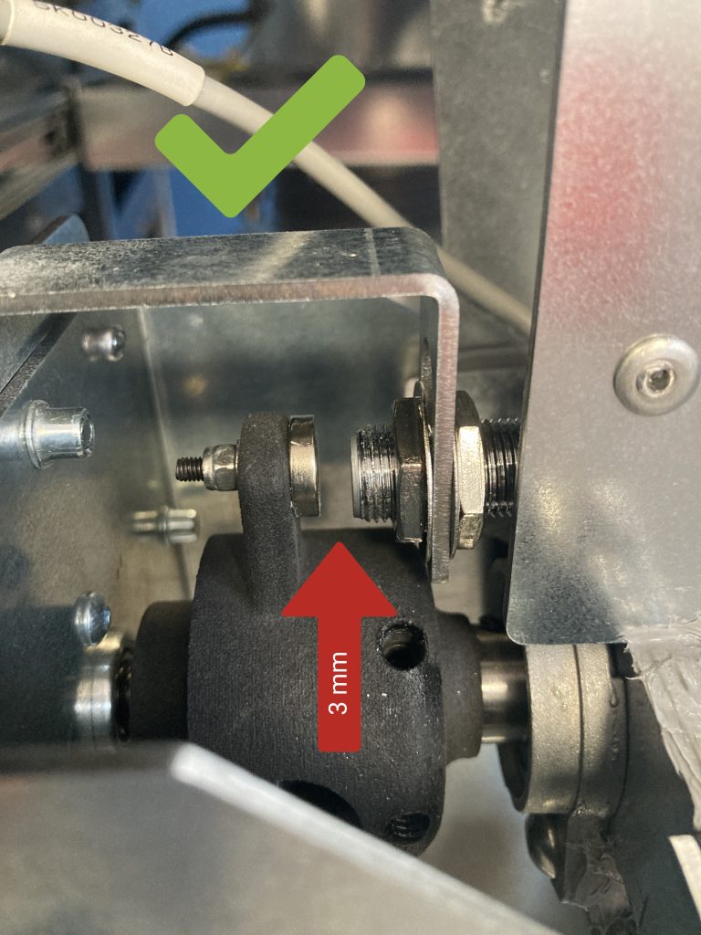
- Adjust the distance between the Hall sensor and the magnets on the clutch. Set the sensor at a distance of 3 mm from the magnet.
- Tighten the nuts securing the Hall sensor. Rotate the clutch to ensure there is no collision with both magnets.
- Connect the power wires to the motor and the Hall sensor.
- Install back cover. Screw the four screws securing the left cover of the device with a 5 mm Allen key.
- Well done. The device is ready for further use.